More Vivitar 283 Hacking

I decided to do more mods to my Vivitar 283: first, add a 250K potentiometer in order to get variable power capability; and second, add a trigger circuit in order to bring down the 110V trigger voltage to something more manageable. I knew that the EOS 350D has a 250V trigger voltage limit, but accessories like the Cactus wireless trigger only have a 12V limit, and besides, I'd feel better with some extra circuitry between the scary high 110V of the Vivitar and my DSLR.

I got the following circuit from Sam's Electronic Flash FAQ:


Lalai and I went to Megamall to do our groceries. It's out of the way but Alexan is there. I went to Alexan and bought the parts (as well as some other stuff like an extra LM1875 and a PCB so I can do some etching).

My Alexan buying experience was fraught with upsets. First, they didn't have any 4M resistors; what they had were 4.3M. Same thing for the 5V zener: they had 5.1V instead. Third, they had no 22nF, 400V capacitors. All their ceramic capacitors were 50V only, they said. So I bought eight 0.1uF capacitors, to put in series, which should give 400V. I don't even know what's the value of eight 0.1uF capacitors in series. Forgot my EE13.

When I got home I had a nasty surprise: the girl at the counter didn't give me any 4.3M resistors or 5.1V zeners. Apparently the blindingly obvious fact that a 5V zener and a 5.1V one, or a 4M resistor and a 4.3M one, are interchangeable, is beyond the ken of Alexan sales staff.

Since I didn't check the parts, I didn't discover that some critical bits were missing until I had the flash in pieces and my soldering iron hot.

Rummaging through my parts bin, I found a couple of 1M resistors and a 15V zener. Since I had no choice, I substituted the 1M for the 4M resistors; and the 15V zener for the 5V one. I knew this would result in a 15V trigger voltage instead of the desired 5V, but 15V is much better than 110V (and presumably the Cactus can survive 15V).


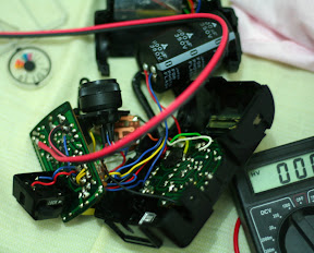
The circuit is very simple, so I just soldered it together point-to-point and covered the exposed wires with heat-shrink tubing and cellophane tape. I put it inside the (now vacated) battery compartment, and rewired the hot shoe to connect to my circuit instead of directly to the flash trigger.

Verifying that trigger voltage is now much, much more manageable:


While I was at it, I also did the potentiometer variable-power mod. This allows me "infinite" gradations of power, but Alexan didn't have any log-taper potentiometers, only linear-taper (another annoyance - but I don't want to go to Raon, so I grit my teeth).

After closing up the case, the ugly tape-wrapped circuit is hidden from view:


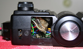
And here's another view, showing the potentiometer mod:


Great success!

Vivitar 283 Hacking

For some reason or another, the Vivitar 283 which I purchased on e-bay stopped working yet again. I thought it was more of the battery corrosion or something, but apparently that wasn't the case.

I first tried modding the battery compartment to run a couple wires in there. But it failed to work. I was getting pretty annoyed at having wasted $30 and the freight forwarding fee; I didn't know why the inverter wasn't working (couldn't hear the inverter whine).

Read through Sam Goldwasser's Strobe FAQ which mentioned that the obvious failure modes in flash inverters are the transformer and the chopper transistor. Now it's been a long long time since EE 25 and I don't think it's possible anyway to test a transistor in-circuit.

Anyway I was cursing my luck and had the strobe in pieces in front of me.


I neglected to note that I had left it on and it was connected to the 6V gel cell.. the outcome is obvious. My finger grazed the huge flash capacitor and I got this sensation like someone had driven a red-hot needle through my finger. Immediately realizing what was going on, I tested the voltage across the flash capacitor with my trusty 165-peso digital multimeter and guess what... 160-odd volts.

Not enough to light the "ready" indicator but enough to give me a small shock. I figured that the inverter was working, but not well enough (nominal flash capacitor voltage is 300-plus volts). So I un-soldered the original wires for the power, and soldered lamp cord directly to the switch and the collector of the chopper transistor:


I used color-coded lamp cord to avoid strobe-destroying accidents. At this point, after powering it up, I could hear the distinctive inverter whine, and the flash would fire when I pressed the test button.

When I put the 283 together, I didn't put the battery compartment in anymore (since with all my screwing around the inside of the strobe, it will never take AA batteries again).


This is OK because I don't intend to use AA batteries (I gave away my AA NiMH batteries to my brother, and I don't want to buy new ones, they're expensive at $5 each).

Here I'm testing the trigger voltage. It's around 110 volts according to my 165-peso multimeter. Well within the capabilities of the EOS 350D (which has a 250V sync voltage). That is, if I trust my $500-plus DSLR to my $4 Chinese-made multimeter.


Final result: it's got that wire dangling out which somewhat interferes with the EOS control dial, but I've got a Quantum power pack on the cheap! I don't have a charger for the 6V gel cell, but a Nokia phone charger should do (it puts out about 7V).


I'd like to think I'm "l33t" for both restoring the Vivitar 283 to good condition; and for wiring up a Quantum-alike battery pack. But the reality is I'm too poor to buy a Speedlite 420EX or something. But the Vivitar 283 will do fine.